Leave Your Message

Top 10 Types of CNC Machined Aluminum Parts

Choosing the right Cnc Machined Aluminum Parts begins with understanding how design, alloy, tooling, and finishing interact.

Aluminum looks easy to machine. It is not always easy.

A sharp end mill may cut through 6061 aluminum smoothly, yet the same tool can struggle with gummy chips in softer alloys. Heat can build near a thin wall. A small mistake in feed rate may leave burrs around a 3-millimeter hole. These details influence strength, appearance, assembly, and production cost.

W. Edwards Deming, a respected manufacturing-quality expert, said, “Quality comes not from inspection, but from the improvement of the production process.” This principle remains useful for CNC machining. Reliable parts come from controlled choices, not from checking defects at the end. Experienced engineers review tolerances, tool access, surface requirements, and material condition before cutting begins.

This introduction examines ten common types of Cnc Machined Aluminum Parts, including housings, brackets, manifolds, heat sinks, panels, and precision prototypes. Each category serves a different purpose. Some protect sensitive electronics. Others guide motion, remove heat, or connect larger assemblies. Their shapes may look simple, but internal pockets and tight datum relationships can make production demanding.

The list has limits. No ranking can fit every industry or application. A compact 7075 bracket may outperform a larger 6061 part in one aircraft assembly, while losing value in a corrosive environment. That contradiction matters. Material strength alone does not define the best component.

Practical judgment matters more.

By comparing geometry, alloy behavior, machining strategy, tolerance control, and finishing options, readers can evaluate these parts with greater confidence. The goal is not to praise aluminum blindly, but to recognize where it performs well and where another material may deserve consideration.
Top 10 Types of CNC Machined Aluminum Parts

Aluminum Enclosures and Covers for Protection and Integration

Top 10 Types of CNC Machined Aluminum Parts

Aluminum enclosures and covers protect sensitive assemblies while supporting clean product integration. They appear in control units, sensor housings, power modules, and compact industrial equipment. CNC machining creates accurate walls, mounting bosses, cable openings, and service panels from solid aluminum blocks or plates. This method supports tight fits around circuit boards and connectors. It also leaves a professional, durable surface.

A well-designed enclosure manages more than appearance. Wall thickness must balance rigidity, weight, and machining time. Internal ribs can reduce vibration without blocking airflow. Sealing grooves accept gaskets around doors or removable covers. Small details matter. A poorly placed fastener may interfere with a connector or make maintenance frustrating. Machinists should check tool access, corner radii, and chip evacuation before production. These checks often prevent expensive revisions.

Aluminum also helps transfer heat away from electronics. Designers may add fins, contact pads, or direct mounting surfaces for thermal control. Conductive finishes can support grounding, but surface treatment requires careful planning around contact points. A sealed cover is not automatically reliable. Pressure changes, uneven gasket compression, or a damaged edge can still create leaks. That deserves testing. In practice, perfect alignment is difficult when thin covers flex during fastening. Using controlled torque and a simple inspection fixture can improve repeatability, although it may not solve every field problem. Good enclosure design accepts these limits and leaves room for inspection, repair, and future integration.
Top 10 Types of CNC Machined Aluminum Parts: Enclosures and Covers for Protection and Integration

The chart compares typical CNC-machined aluminum wall-thickness design ranges for ten enclosure and cover applications. Values are representative engineering guidelines based on common aluminum machining practices; final dimensions depend on enclosure size, load, sealing requirements, heat dissipation, and alloy selection.

Aluminum Brackets and Frames for Structural Support

Top 10 Types of CNC Machined Aluminum Parts

Aluminum brackets and frames provide reliable structural support in equipment, enclosures, robotics, and light industrial assemblies. Their strength-to-weight ratio helps reduce unnecessary mass without making the structure feel fragile. The 2024 U.S. Geological Survey Mineral Commodity Summaries estimated global primary aluminum production at about 70 million metric tons in 2023. That scale supports stable material availability, but alloy selection still matters.

In practical machining, 6061 aluminum suits general brackets and frames because it balances strength, machinability, and corrosion resistance. For higher loads, engineers may consider stronger heat-treated alloys. A bracket can look perfect and still fail at a sharp internal corner. Add generous fillets, maintain consistent wall thickness, and position fastener holes away from thin edges. CNC milling can hold tight dimensions, yet tolerance should match the actual load path. Over-tolerancing every feature increases cost. I still see this mistake in early designs.

Tips: Check the load direction before finalizing the geometry. Use ribs where bending is likely. Leave tool access around deep pockets. Confirm the alloy, temper, surface treatment, and inspection method on the drawing. The International Aluminium Institute reports that recycled aluminum requires far less energy than primary production, so designs should support repair, separation, and future recycling where practical. A small design review can prevent a costly redesign.

Aluminum Plates and Flanges for Precision Assembly

Among common CNC-machined aluminum parts, plates and flanges support precise assembly. They position housings, guide fasteners, and maintain stable contact between components.

Machining experience shows that flatness matters as much as thickness. A plate may measure correctly at four points yet bow near its center. This is where inspection must move beyond nominal dimensions. Aluminum alloy selection also affects stiffness, weight, and surface behavior. One alloy may machine cleanly but offer less resistance to deformation.

For plates, pocket depths, hole patterns, and edge distances require careful planning. Flanges need special attention around bolt circles, bores, and sealing faces. A bore can be accurate, but poor perpendicularity may still create assembly stress.

I have seen this happen after inadequate workholding. The drawing was correct. The setup was not.

Deburring prevents raised edges from disturbing contact surfaces. Surface treatment can improve wear and corrosion resistance, but coating thickness may affect holes and fits. That assumption can cause avoidable rework. Calibrated tools, inspection records, and controlled machining conditions improve reliability.

Operators should also check the part after release from the fixture, not only while clamped. Some distortion appears late. Leave room for that possibility.

Aluminum Shafts and Couplers for Rotational Applications

Aluminum Shafts and Couplers for Rotational Applications

Aluminum shafts support rotating loads in compact machinery, automation modules, pumps, and positioning systems. Their low weight helps reduce inertia, especially during frequent starts and stops. CNC machining can produce precise diameters, keyways, threads, and bearing seats from one controlled setup. That matters when a shaft must run smoothly inside a small housing.

Couplers connect two shafts while transferring torque between them. Rigid couplers suit aligned assemblies, while flexible designs can absorb minor angular or parallel errors. However, “minor” needs measurement. Excessive misalignment can create vibration, heat, and early fatigue. Experienced machinists check concentricity, runout, and surface finish before assembly. A fine finish may help at bearing seats, but every surface does not need polishing. That choice can increase cost without improving performance. Hard-anodized surfaces may improve wear resistance, although the process can slightly change critical dimensions.

Tips: Specify torque, speed, shaft diameter, and operating temperature before machining. Leave enough wall thickness around keyways and cross-holes. Balance longer shafts after machining, especially above moderate speeds. Inspect with calibrated gauges, not visual judgment alone. Keep coupling bores clean during installation. A small burr can affect alignment. Also, review the design after testing; the first version may work, but it may not be the best version.

Top 10 Types of CNC Machined Aluminum Parts - Aluminum Shafts and Couplers for Rotational Applications
Rank Part Type Typical Aluminum Alloys Rotational Function Common Design Features Typical Machining Tolerance Suitable Applications
1 Stepped Aluminum Shafts 6061-T6, 6082-T6 Transmit torque while supporting bearings, gears, pulleys, or seals at different diameters.
  • Multiple precision diameters
  • Shoulders for axial positioning
  • Keyways, flats, or retaining-groove details
Typically ±0.02 to ±0.05 mm on critical turned diameters Compact drives, rollers, laboratory equipment, automation assemblies
2 Keyed Drive Shafts 6061-T6, 7075-T6 Transfer torque through a parallel key between a shaft and a hub, gear, pulley, or sprocket.
  • Standard or custom keyway
  • Concentric bearing journals
  • Chamfered ends for assembly
Typically ±0.02 to ±0.05 mm for journals; keyway dimensions depend on the design standard Motor-driven mechanisms, conveyors, pumps, indexing systems
3 D-Shafts 6061-T6, 6082-T6 Provide positive anti-rotation in low-to-moderate torque connections without a separate key.
  • One longitudinal flat
  • Simple clamp or set-screw installation
  • Reduced assembly part count
Typically ±0.03 to ±0.08 mm on the round diameter and flat location Encoder drives, small actuators, adjustable knobs, light-duty robotics
4 Hollow Aluminum Shafts 6061-T6, 6082-T6 Reduce rotating mass and inertia while retaining useful torsional stiffness for a given envelope.
  • Precision internal bore
  • Uniform wall thickness
  • External bearing and coupling seats
Typically ±0.03 to ±0.08 mm for critical external features; bore tolerance is application-specific High-speed spindles, gimbal systems, rollers, lightweight drive assemblies
5 Rigid Sleeve Couplers 6061-T6, 6082-T6 Join two aligned shafts while maintaining a fixed angular and axial relationship.
  • Two coaxial bores
  • Clamp screws or radial set screws
  • Keyways or flats where higher torque transfer is required
Typically ±0.02 to ±0.05 mm on bore diameter for accurate shaft fits Aligned motor shafts, sensor assemblies, linear motion drives, compact machinery
6 Flexible Beam Couplers 7075-T6, 6061-T6 Transmit torque while accommodating limited angular, parallel, and axial misalignment.
  • Slotted or spiral flexure geometry
  • Single-piece construction
  • Clamping hubs for low backlash
Typically ±0.02 to ±0.05 mm on hub bores; flexure performance depends strongly on slot geometry Encoders, servo systems, precision positioning equipment, inspection devices
7 Oldham-Style Couplers 6061-T6, 7075-T6 Compensate for parallel shaft offset using two hubs and a center sliding disc.
  • Three-piece coupling arrangement
  • Crossed slots in the hubs and disc
  • Replaceable wear element in many designs
Typically ±0.02 to ±0.05 mm on hub bores and mating features Motion-control systems, compact stages, lead-screw drives, instrumentation
8 Flanged Shaft Couplers 6061-T6, 6082-T6 Connect shafts through a face flange, allowing convenient axial assembly and service access.
  • Integral mounting flange
  • Precision pilot diameter
  • Through-holes or threaded mounting holes
Typically ±0.03 to ±0.08 mm on pilot and bore features Modular machinery, gearboxes, rotary tables, actuator interfaces
9 Threaded and Tapped Shaft Ends 6061-T6, 7075-T6 Provide a compact method for retaining hubs, bearings, discs, or rotating accessories.
  • Internal or external threads
  • Retaining-nut shoulder
  • Center-drilled or chamfered end
Typically ±0.05 to ±0.10 mm for general thread-related dimensions; fit class should be specified Fan assemblies, wheel hubs, laboratory fixtures, removable rotating modules
10 Multi-Feature Rotor Hubs 6061-T6, 7075-T6 Mount rotating discs, impellers, pulleys, fans, or sensors directly to a shaft.
  • Central bore and shoulder
  • Balanced bolt-circle pattern
  • Keyway, clamp interface, or threaded holes
Typically ±0.02 to ±0.05 mm on bore and pilot features; balance requirements vary by speed Fans, impellers, optical rotors, compact spindles, centrifugal mechanisms

Aluminum Manifolds and Heat Sinks for Functional Performance

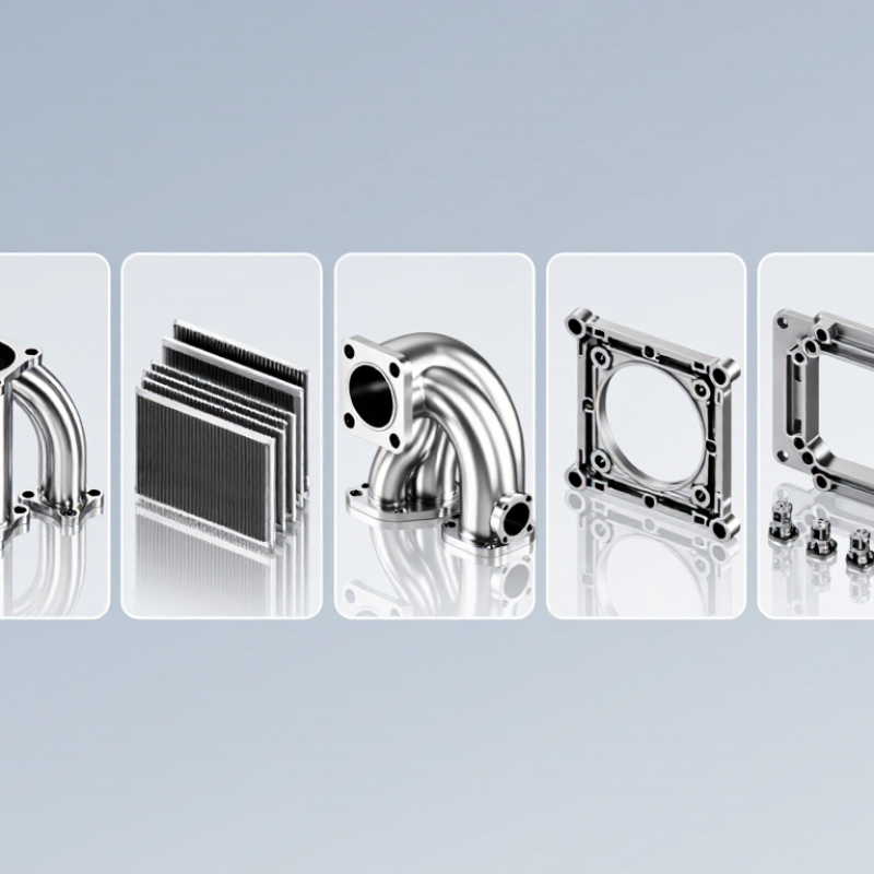
Among the top ten types of CNC machined aluminum parts, manifolds stand out for functional performance. They distribute air, oil, or coolant through accurately positioned passages. CNC machining maintains tight port locations and consistent sealing surfaces. In production work, engineers inspect each manifold against the fluid path drawing. A small error can restrict flow.

It matters.

Aluminum heat sinks manage thermal loads in power electronics, lighting, and compact control systems. Their fins increase surface area, while the base transfers heat from the mounted component. Machining can create flat mounting faces, threaded holes, and tailored fin patterns. Fins that are too thin may bend during handling. Fins that are too thick may reduce cooling efficiency. The correct balance depends on airflow, available space, and operating temperature.

Material selection also affects reliability.

Common aluminum alloys offer useful strength, machinability, and thermal conductivity, but none performs perfectly in every design. Surface treatments may improve corrosion resistance, yet they can change dimensions slightly. Reliable suppliers verify critical features with coordinate measuring equipment and pressure-test fluid manifolds when required. Engineers should review burr removal, chip clearance, and cleaning procedures before assembly. These details seem minor. They are not. A design can look precise while still creating maintenance problems in the field.